
Furnaces and soaking equipment
Rigid and encapsulated formats add compact resistance behind large refractory surfaces and covers.
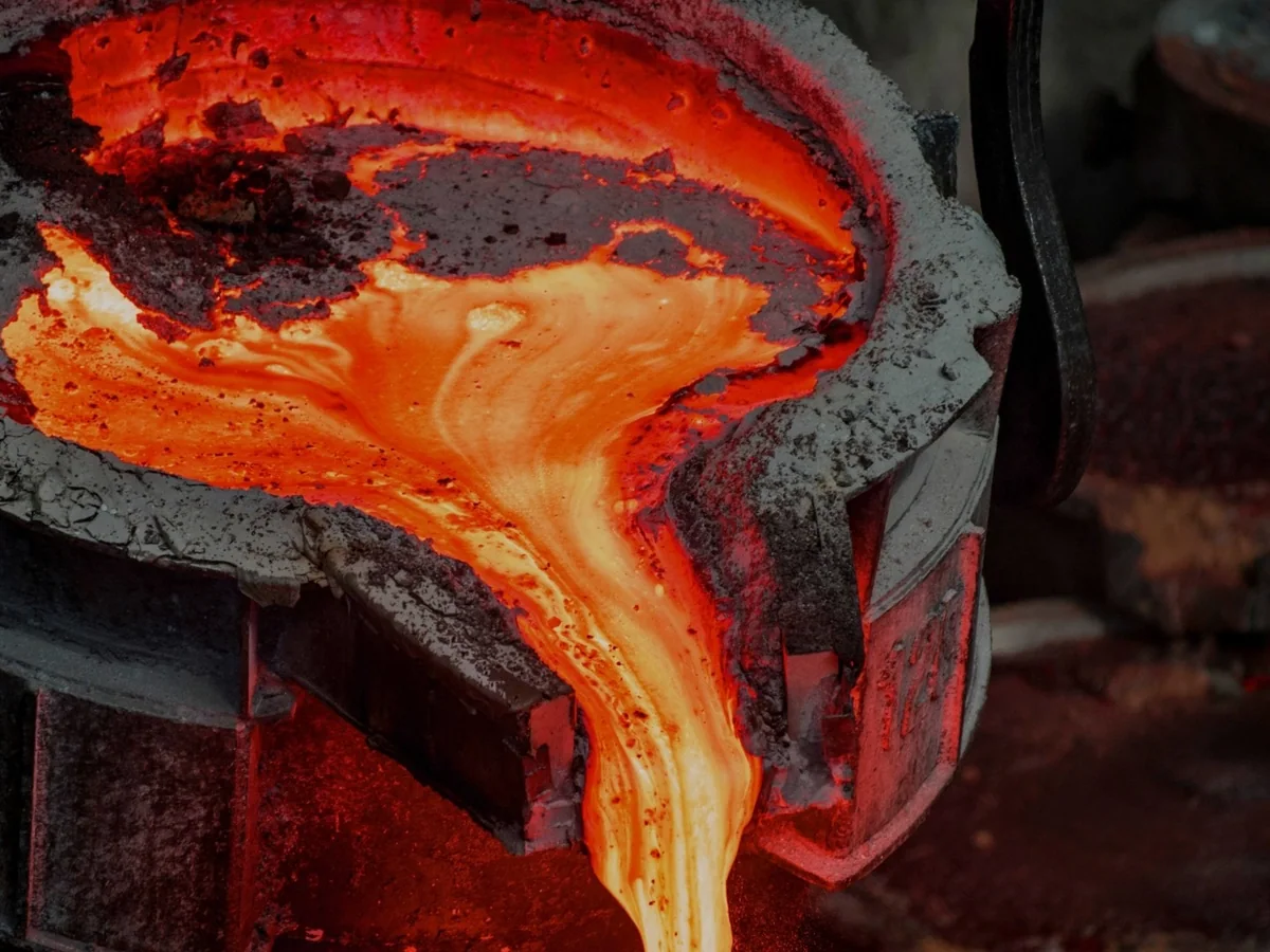
Iron, steel and process equipment
Siltherm brings compact thermal resistance behind refractory linings and around high-temperature equipment where conventional insulation takes too much space.
Process heat map
The product form follows the lining, pipe or access conditions around the equipment.
Rigid and encapsulated formats add compact resistance behind large refractory surfaces and covers.
Flexible formats follow curved walls and base transitions while preserving space for the working lining.
Preformed and flexible insulation follows steam, oil, gas and hot-air lines, including bends and changing profiles.
Flexible or pourable formats cover complex voids and equipment zones that still need practical access.
Space-efficient lining design
Compact microporous backup reduces heat flow through the refractory build-up while preserving space for the working lining.
High-temperature duty starts at the process boundary.
The refractory provides structure, wear allowance and mechanical support.
Rigid, encapsulated or flexible formats add resistance in limited space.
The protected boundary supports safer surrounding conditions and lower heat loss.
Equipment applications
Flat linings favour rigid formats. Curved vessels need insulation that follows the shell.
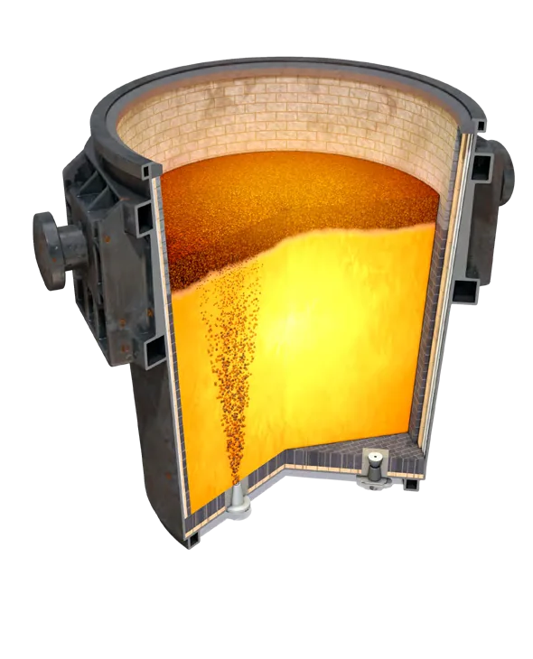 01
01Thin flexible backup follows curved walls and base transitions while retaining valuable process heat.
Explore the AluFlex route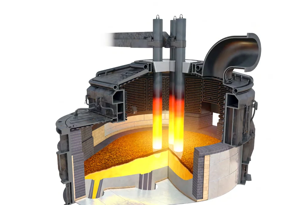 02
02Rigid or encapsulated formats bring compact thermal resistance to large lining areas.
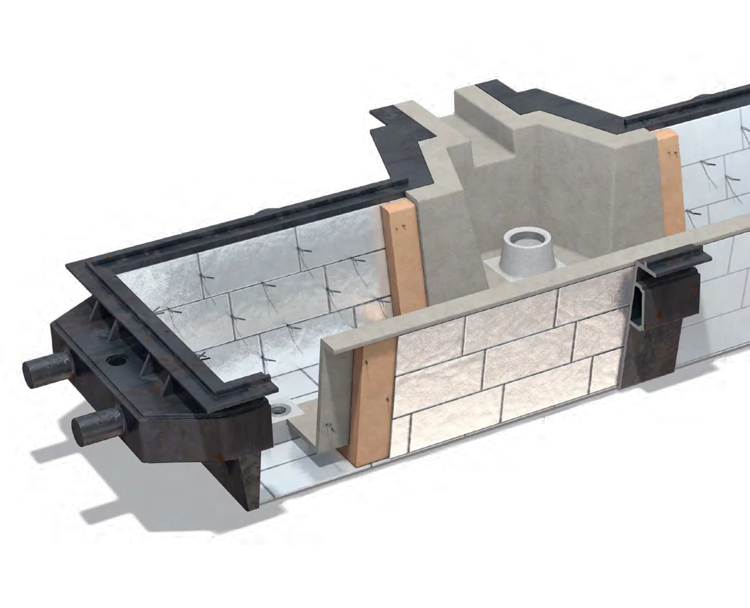 03
03Configured panels maintain coverage through shallow vessels, joints and local penetrations.
AluFlex in ladle linings
AluFlex follows the curved wall and base transition behind the refractory. Its thin aluminised construction preserves lining space and is straightforward to handle on site.
Explore Siltherm AluFlexProduct routes for high-temperature equipment
Rigid formats cover defined lining areas. Flexible, preformed and pourable formats handle curves, pipes and difficult voids.
Discuss your high-temperature equipment
Tell us the equipment type, operating temperature and available space. We will identify the relevant rigid, flexible, preformed or pourable format.
Discuss a high-temperature application